Final Project
the tension tester
-
-
Note: for detailed information on the Tension Tester software, along with code snippets and downloadable files, please see the Week 10 assignment.
-
Background
-
Load Cells
-
Feats of Strength
-
One of the most popular training tools to increase hand and finger strength in climbing is known as a hangboard (or fingerboard). Hangboards are oft made of plastic or wood and have a variety of holds to hang from and train on. By slowly increasing the duration of a hang or the shallowness of the holds you hang from, you can train and track improvement in finger and hand strength.
Tracking your progress in climbing, though, can be hard as the difficulty between grades increases. Though finger and pulling strength is not the most important factor in your climbing journey, it can be a good indicator of improvement. You often hear the phrase, "Numbers aren't important." But to that I say, "Why does my self worth rely entirely on them, then?" How can you obtain a more accurate measure of your strength and also get your fix of sweet, sweet numerical validation? -
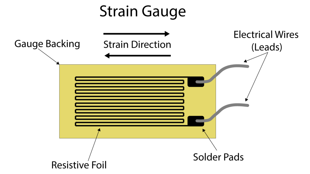
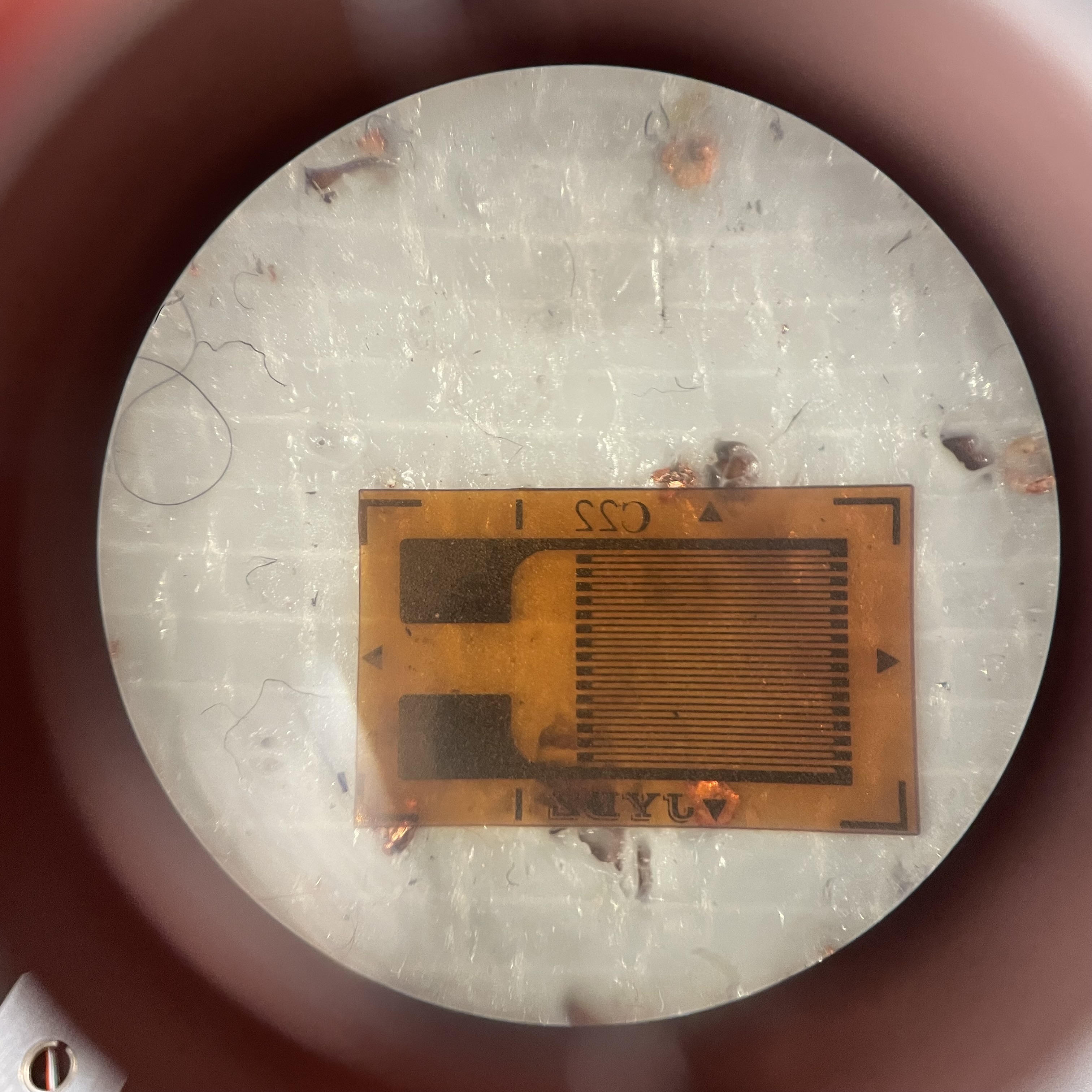
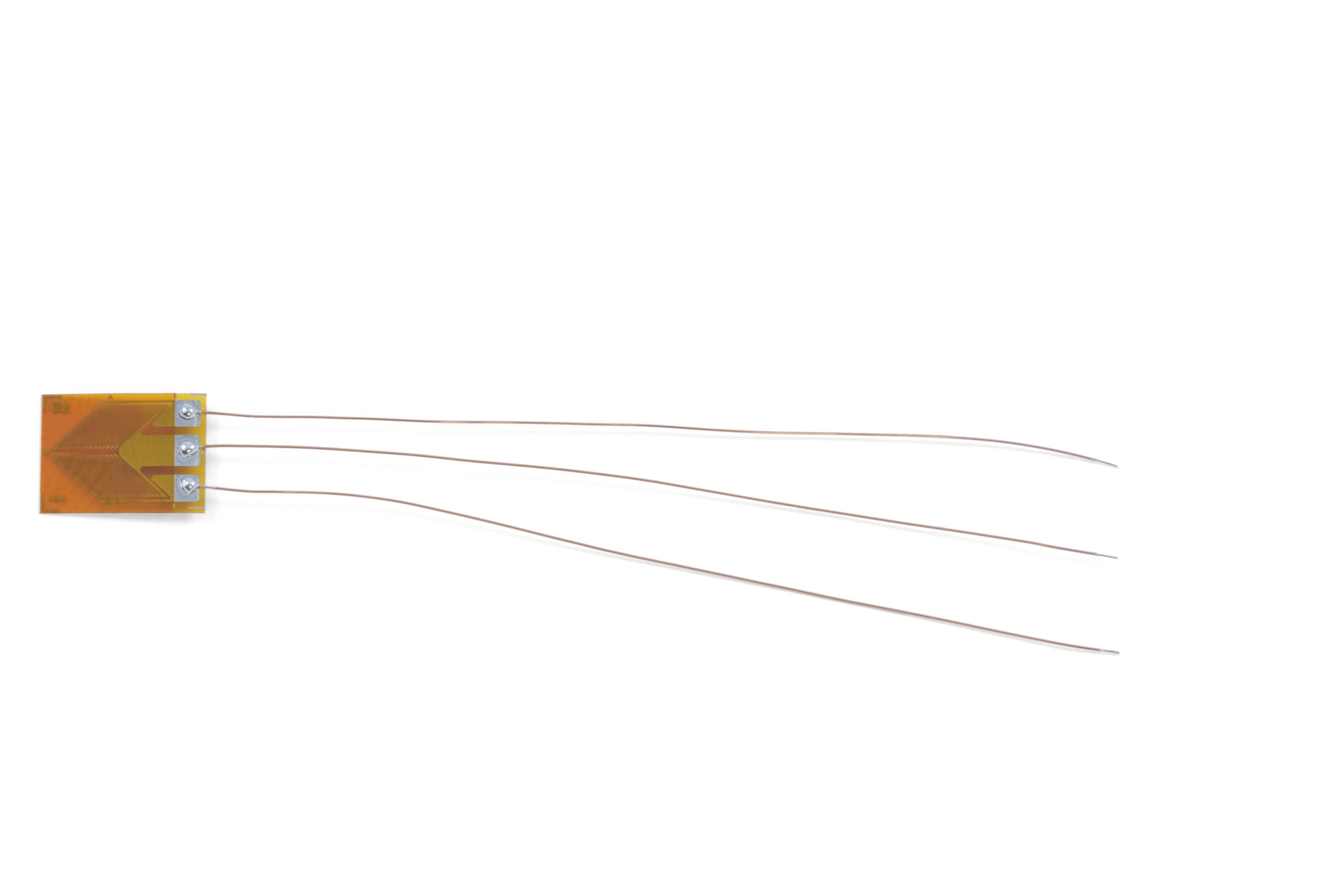
The foundation of the Tension Tester is a load cell. What is, then, a load cell? A load cell is a type of sensor used to measure force or weight. It typically consists of a metal body with strain gauges attached that detect the deformation caused by a load applied to the cell, which is then converted into an electrical signal proportional to the applied force. The metal body is often made of a flexible yet strong metal such as aluminum. What, then, is a strain gauge? A strain gauge is, at its essence, a coiled wire. As the object that the strain gauge is adhered to deforms, the strain gauge's metal foil or wire also deforms, causing a change in its electrical resistance, which can be measured and used to calculate the force applied to the object. The change in resistance (and therefore voltage) is, according to the beautiful laws of physics, linear. Below are photographs of a diagram of a strain gauge, a strain gauge under a microscope, and an S-type load cell from a hanging scale.
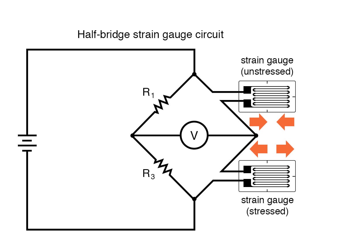
For this project, I attempted to create my own load cell using 2 half-bridge strain gauges. A half bridge strain gauge is simply two strain gauges with one end of the wires on each connected to each other such that they form half of a Wheatstone Bridge. A Wheatstone Bridge is simply a particular configuration of resistors (in this case, each strain gauge is a resistor) such that changes in resistance are easier to measure and readings are averaged out among multiple strain gauges to increase accuracy. Though I did not photograph my attempt at the full load cell and the resultant failure due to oversight and a time crunch, I did document the creation of the load body cell itself.
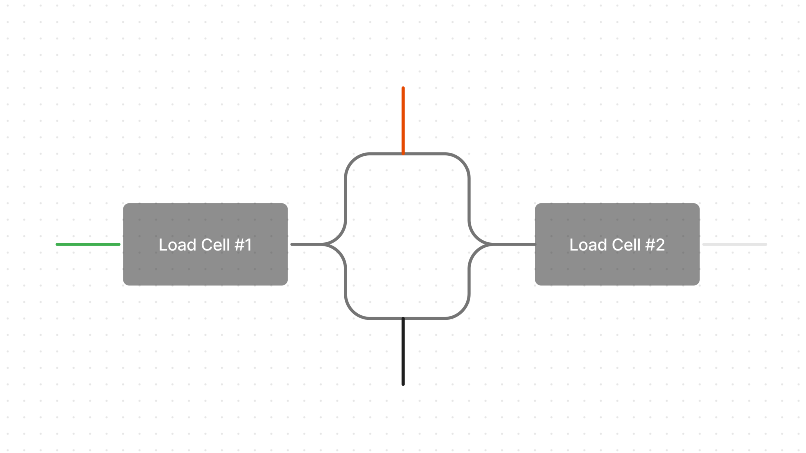
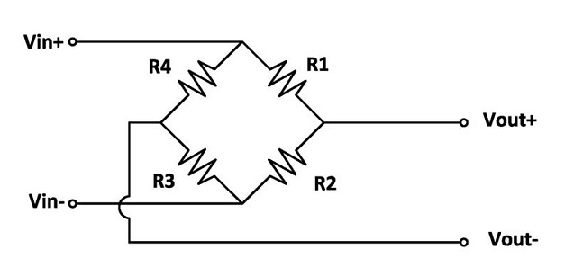
Should you want to create a full-bridge S-type load cell using two half-bridge strain gauges, simply do the following. Take your two, three-wire half-bridge strain gauges and arrange them such that they are symmetric and each of their wires touch. The portion where the top two wires meet is now the RED load cell wire. The bottom is the BLACK. The middle left wire is the GREEN, and the middle right is WHITE. See the diagram below:
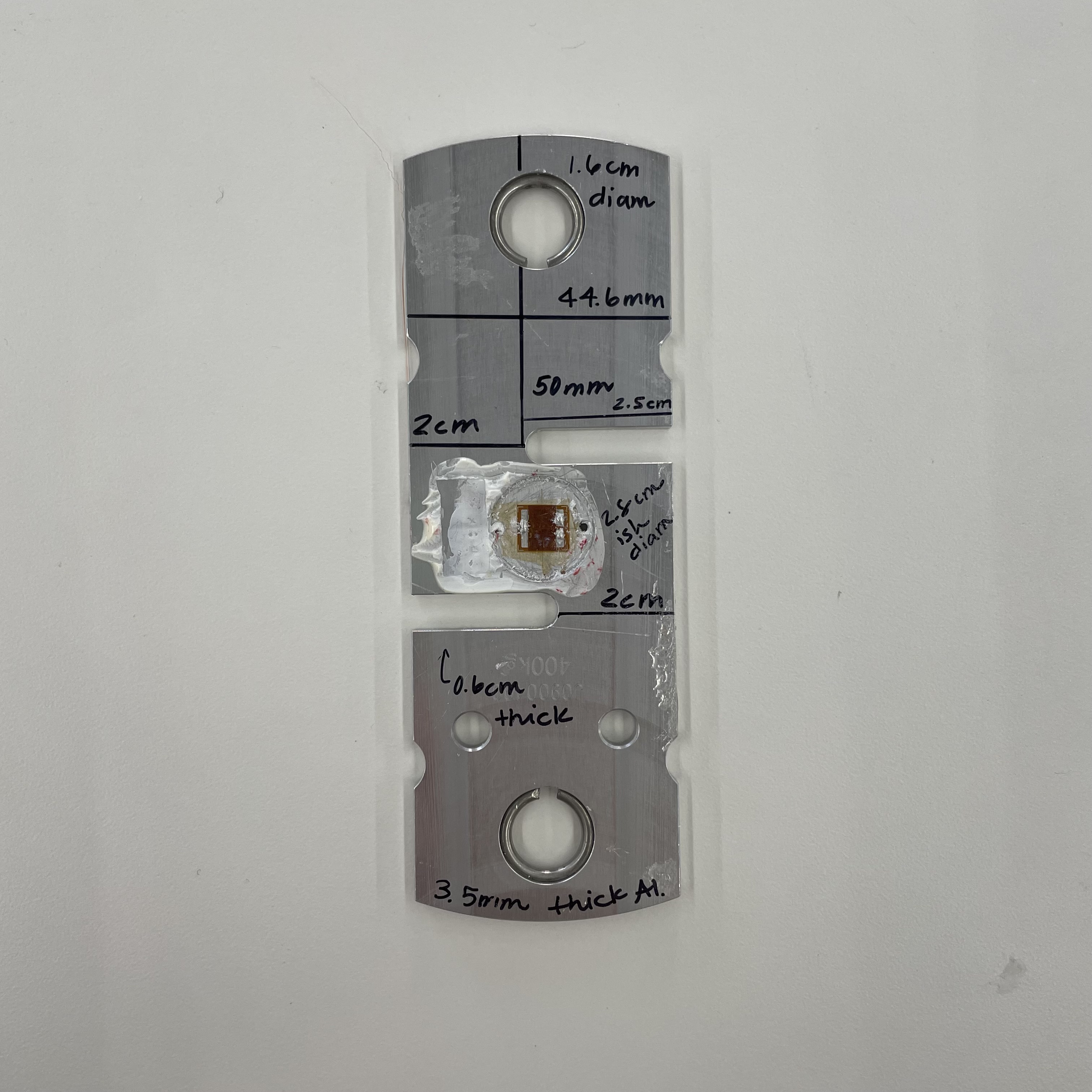
Now, cut your load cell using the water jet cutter. (Note: all files are available for download at the bottom of this page.) Using a mill, make a small divot at the center of the load cell on each side and two small holes in it, as pictured below. Place one half-bridge strain gauge on one side, and another on the other side. Tape down the strain gauges, and thread the wires through the small holes. Solder and join to make a wheatstone bridge with four output wires, as detailed above. Using epoxy glue, adhere the strain gauges to the load cell body. -
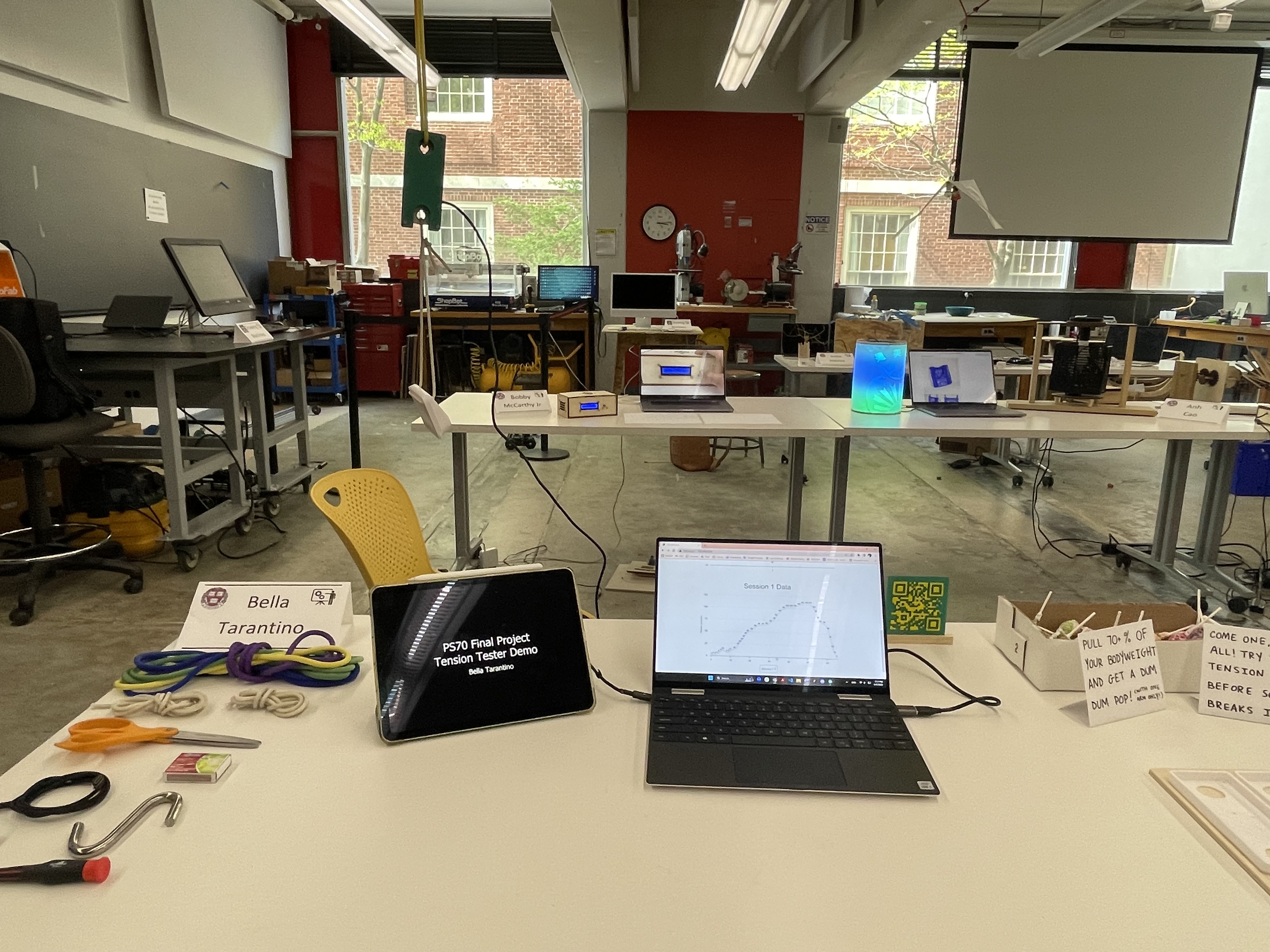
For my final project setup, I thought it would be fun to have people interact with my
project as much as possible. To faciliate this, I went for a carnival game vibe where,
if a passerby stuck around long enough to hear my spiel, they could weigh in, have a few
goes at the tension tester, and, if they could pull 70% or more of their bodyweight with
ONE arm, they won a Dum Dum Pop. I was a bit worried about asking people to weigh in,
but I made sure to explain that weighing in and competing for a lolipop was entirely
optional, and multiple people politely declined the offer to weigh in but still had a go
at the Tension Test. Anyways, it was a lot more popular than I anticipated, and I got
lots of folks to give it a try. Shoutout to my classmate Lane who holds the record for
"highest percentage of bodyweight pulled" at over 100% (he can almost do a one-arm
pull-up). About 5 or 6 people were able to pull more than 70% of their bodyweight, less
than anticipated, but most folks were able to pull more than 50%, which I thought was
interesting. A few folks who stopped by told me about Lattice Training for climbing,
which apparently utilizes the exact same device I made.
-
The Tension Tester
-
The Body
-
Thank you!
-
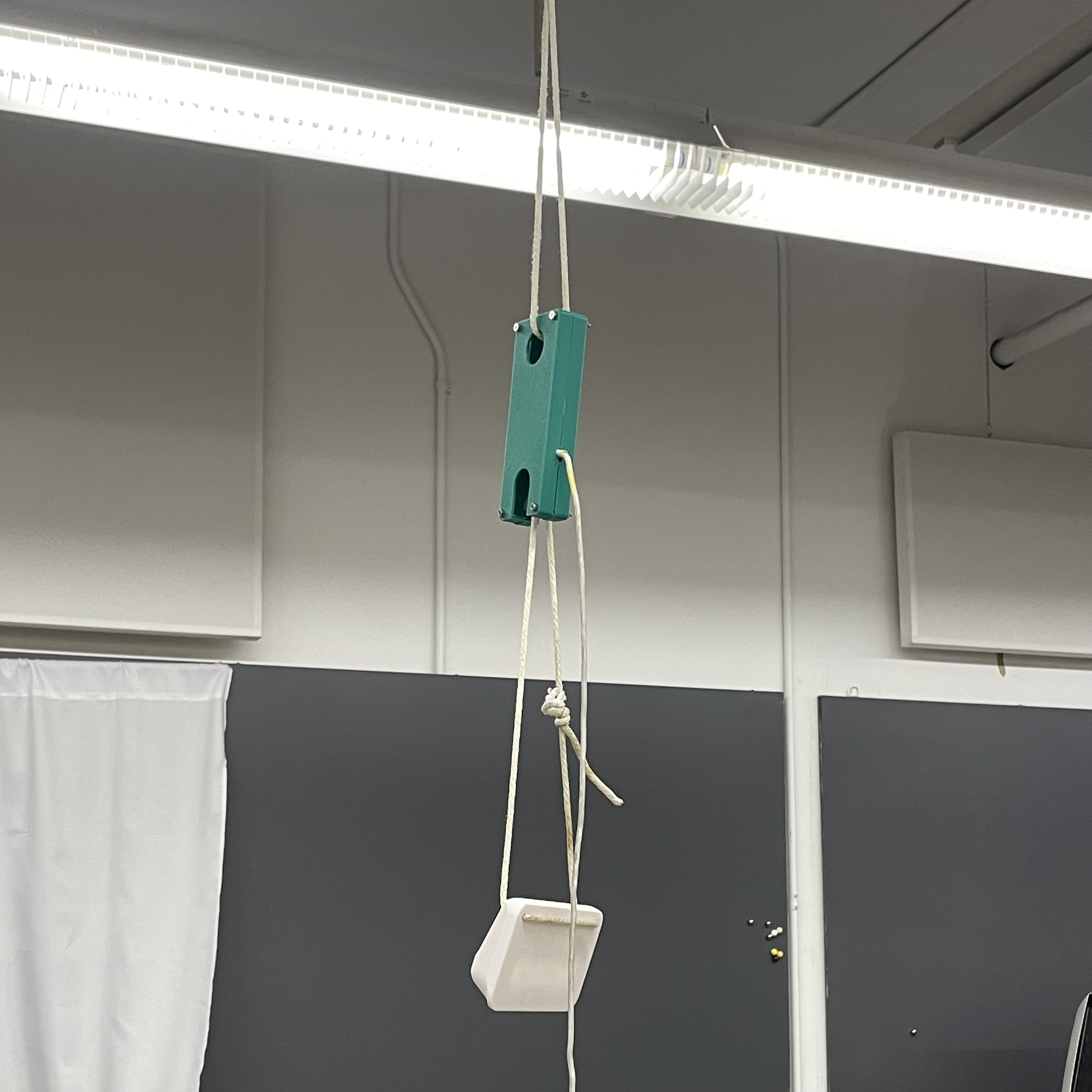
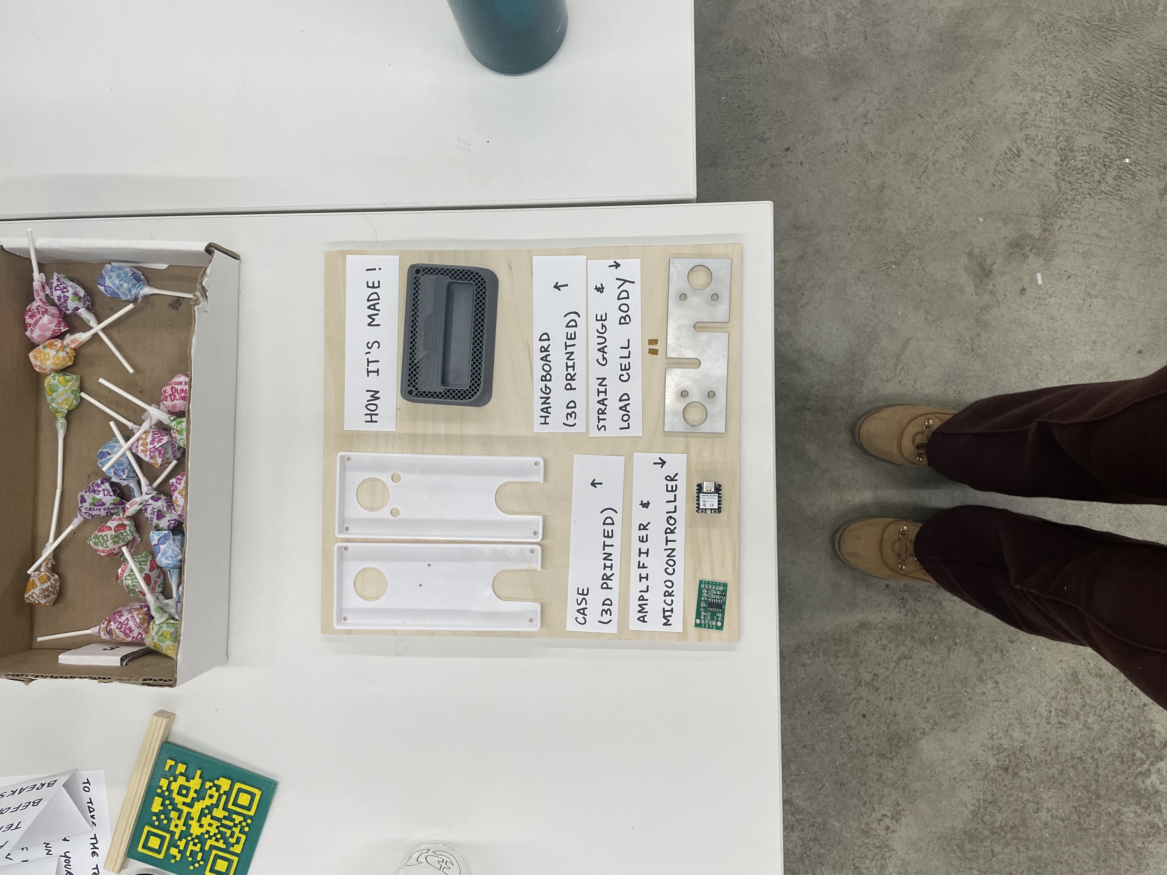
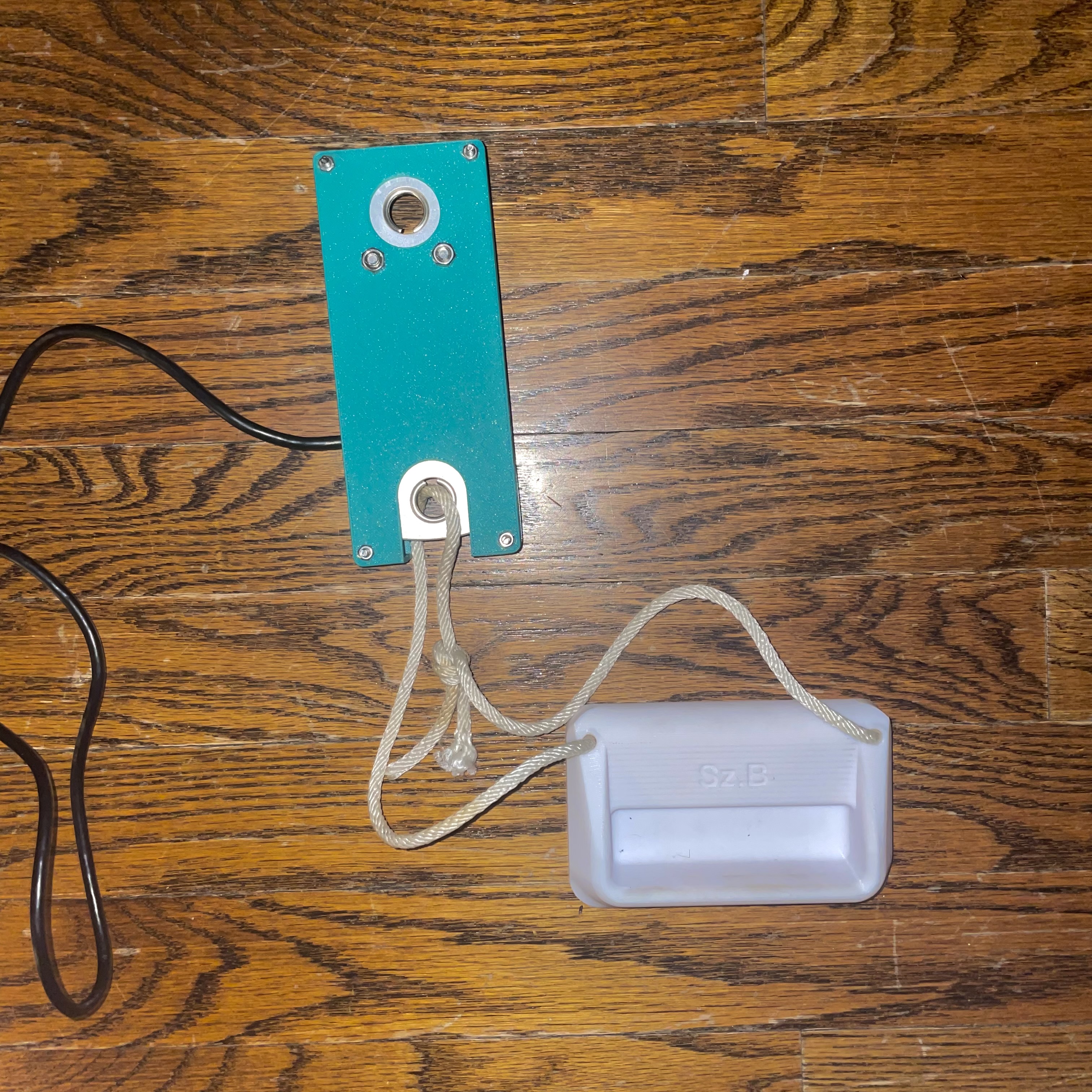
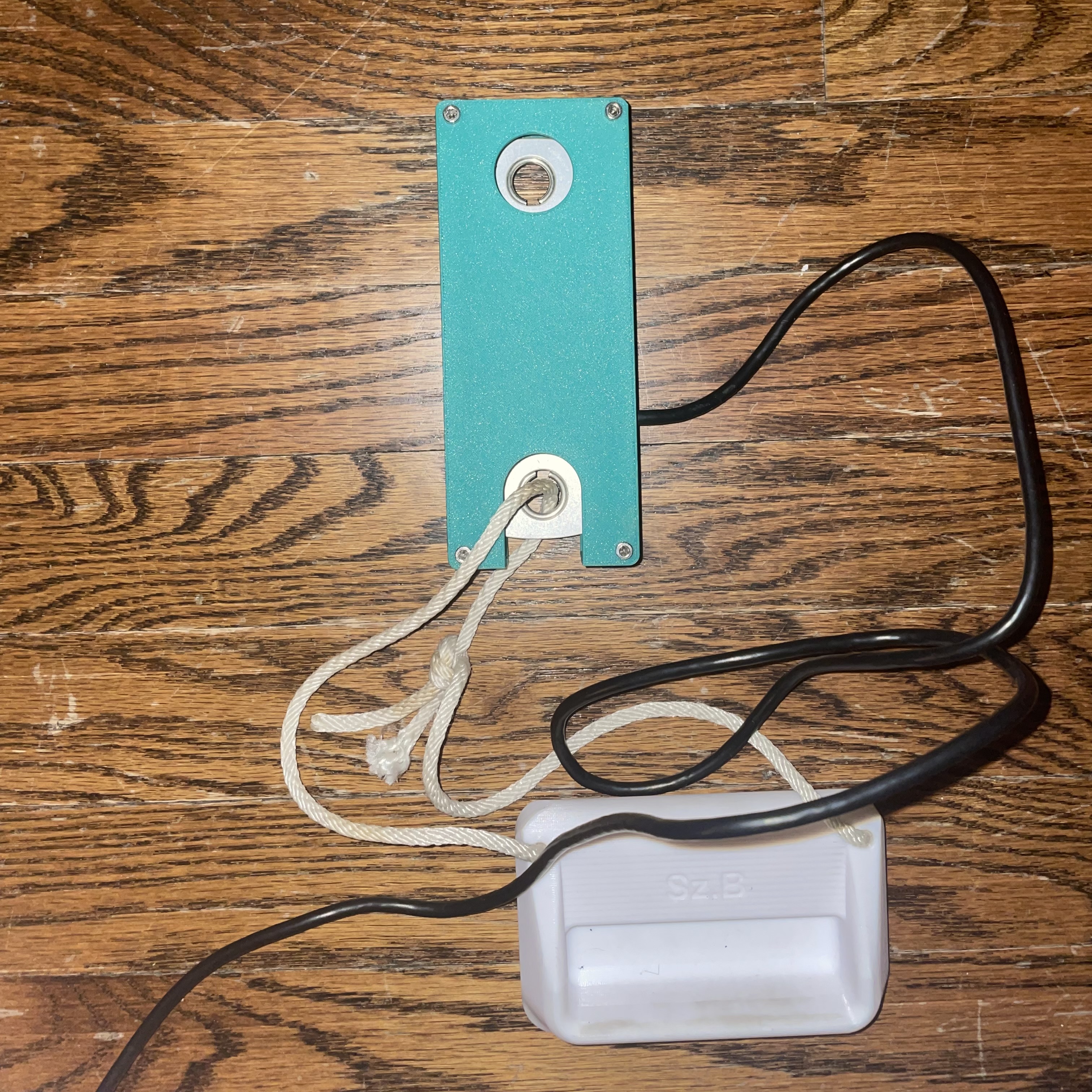
My final project, the Tension Tester (pictured above, below, and in many other places), helps climbers measure their pulling and finger strength in a few steps. Simply connect the Tension Tester to your local WiFi, tie it to a pull-up bar or ceiling beam, connect your fingerboard, and pull! While the Tension Tester is on, live force readings will display on its web app, identifying both individual "pulling sessions" and your maximum force across them. This tool allows you to measure your maximum pulling force, see how quickly it decays, and track your progress over time.
-
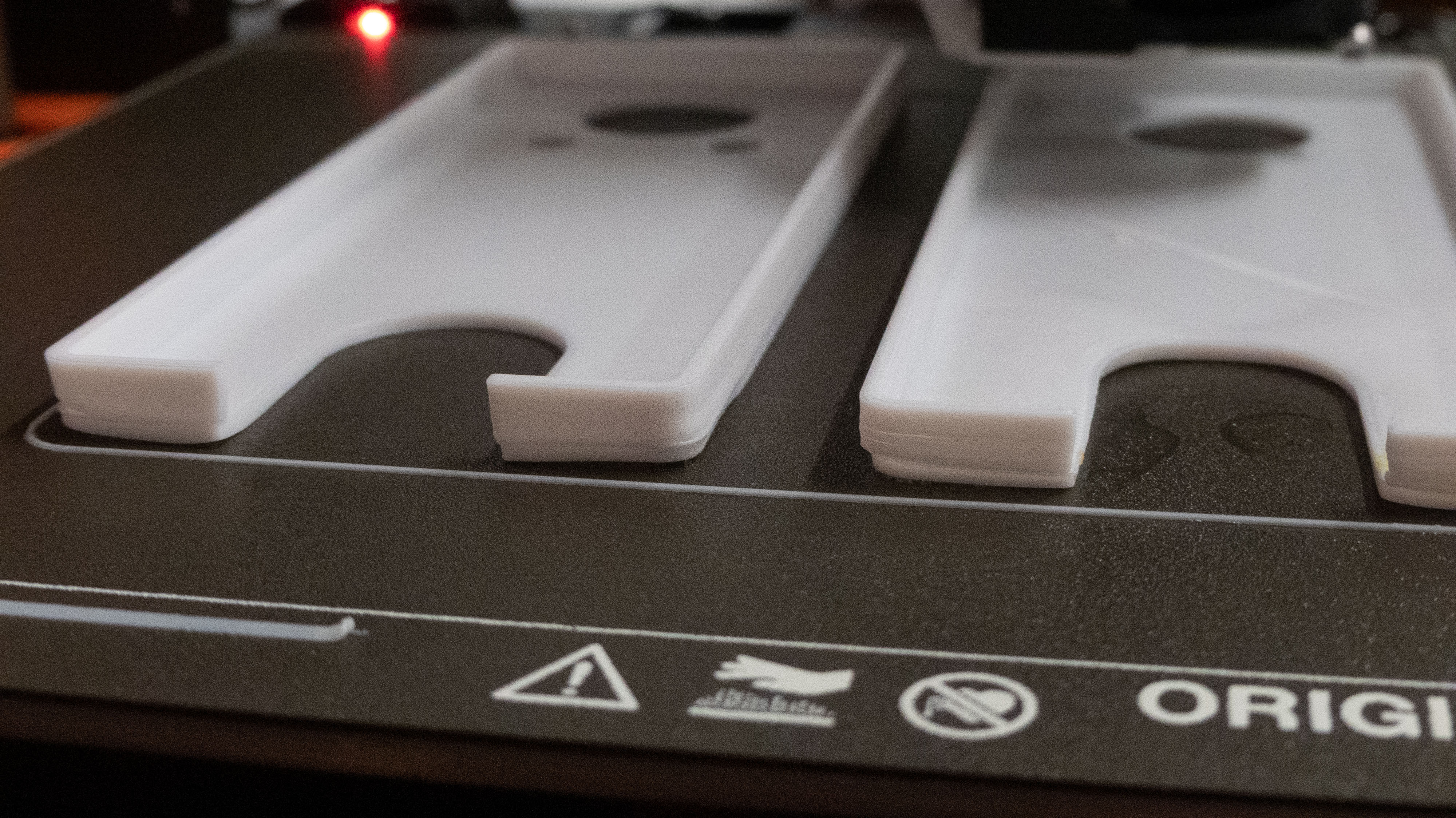
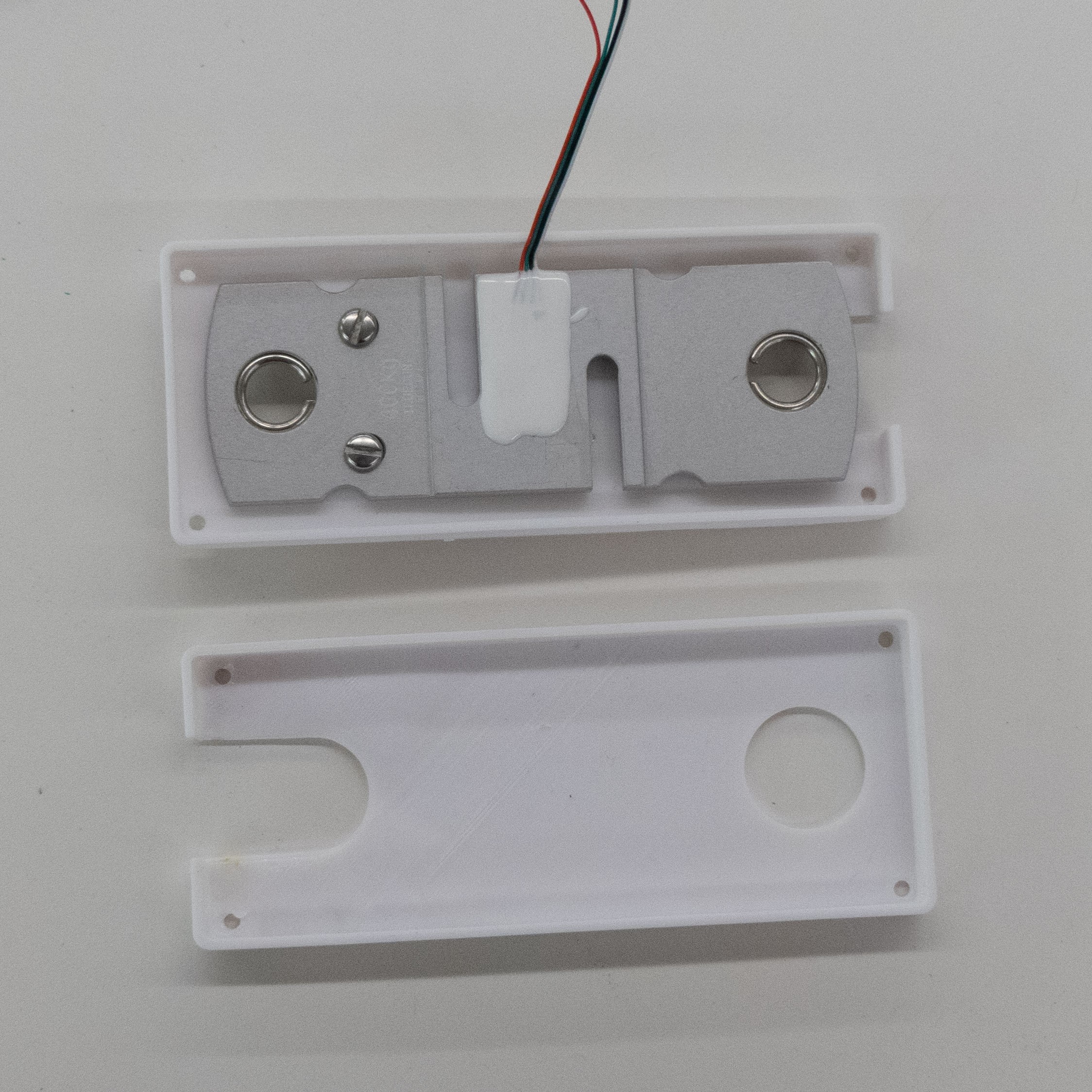
The body for the Tension Tester was a challenge, as my skills in Fusion 360 were not as honed. Because I used a load cell from a hanging scale, I simply took measurements from the load cell; primarily, the distance from the top of the load cell to the center of the holes at the top and bottom, along with the distance from the sides of the load cell to the center of the screwholes, and the dimensions of the load cell overall. This allowed me to make a case that closed properly, had a place to mount the load cell onto to prevent it from moving, and that had openings for the users to hang the device from a wall or bar. After modeling the load cell in Fusion 360, I was able to make a case for and 3D print it using PLA filament. Instead of relying on screws, I used nuts and bolts, which I think gave the case a cool, rugged look. Below are a few photos of the case in progress (along with the failed print) and all put together.
The body should take approximately 4 hours to print. This print had a lot of trouble staying on the bed, so I suggest raising the heat to 75-80 degrees and slowing down the speed of the first layer to about 90% to ensure a quality base and prevent curling.
-
I just wanted to include a small display of my gratitude somewhere on the website. This has been such an outstanding class. I've never had more fun or had more freedom to just MAKE things. It's such a blessing. Nathan is such a kind, genuine, and helpful teacher, and his good vibes transferred well to the class, who bonded like I've never seen in any of my other courses. Every week was a hoot, and I'm recommending this class to everyone I know. Thanks for doing what you do, and thanks for making this semester an amazing one.
-
The Circuitry
-
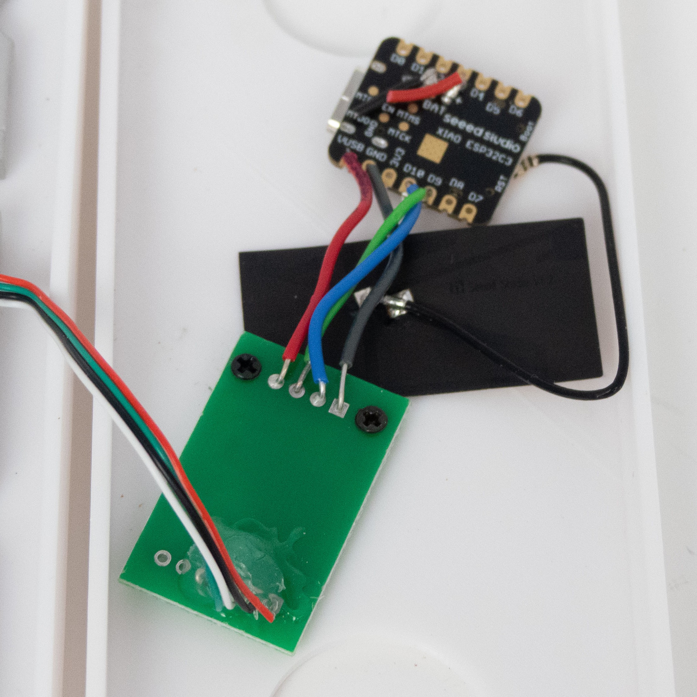
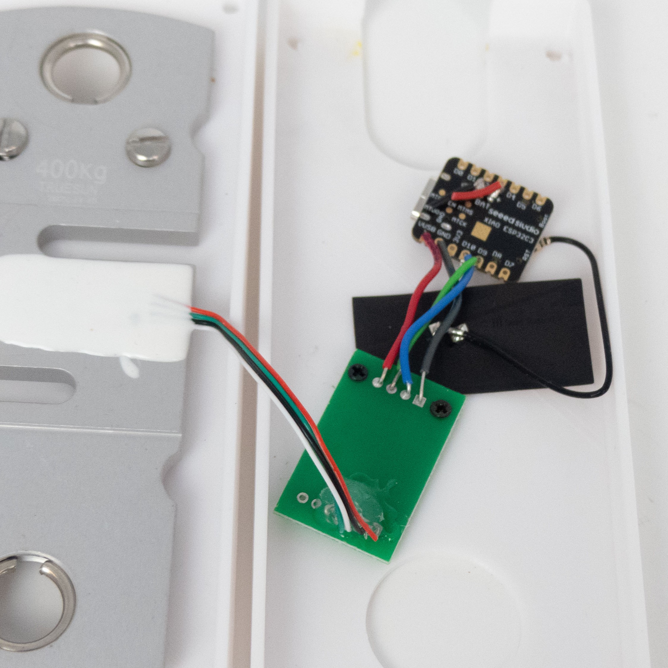
The actual Tension Tester hardware is fairly simple. It is just a load cell, an amplifier, and an ESP32 Xiao. The connections between the ESP32 Xiao, load cell, and amplifier go as such:

The load cell here is pictured with four wires (red, white, black, and green) as discussed in the Load Cell section. The load cell pictured is not an S-type and is primarily for compression rather than tension, but the wiring is the same. We connect the red wire to E+, black to E-, white to A-, and green to A+ on the HX711 amplifier. We then feed DT and SCK to data pins of our choice, while GND and VCC go to GND and 5V, respectively. For my project, I connected SCK and DT to D9 and D10, respectively, on the ESP32 Xiao.
-
The Hangboard
-
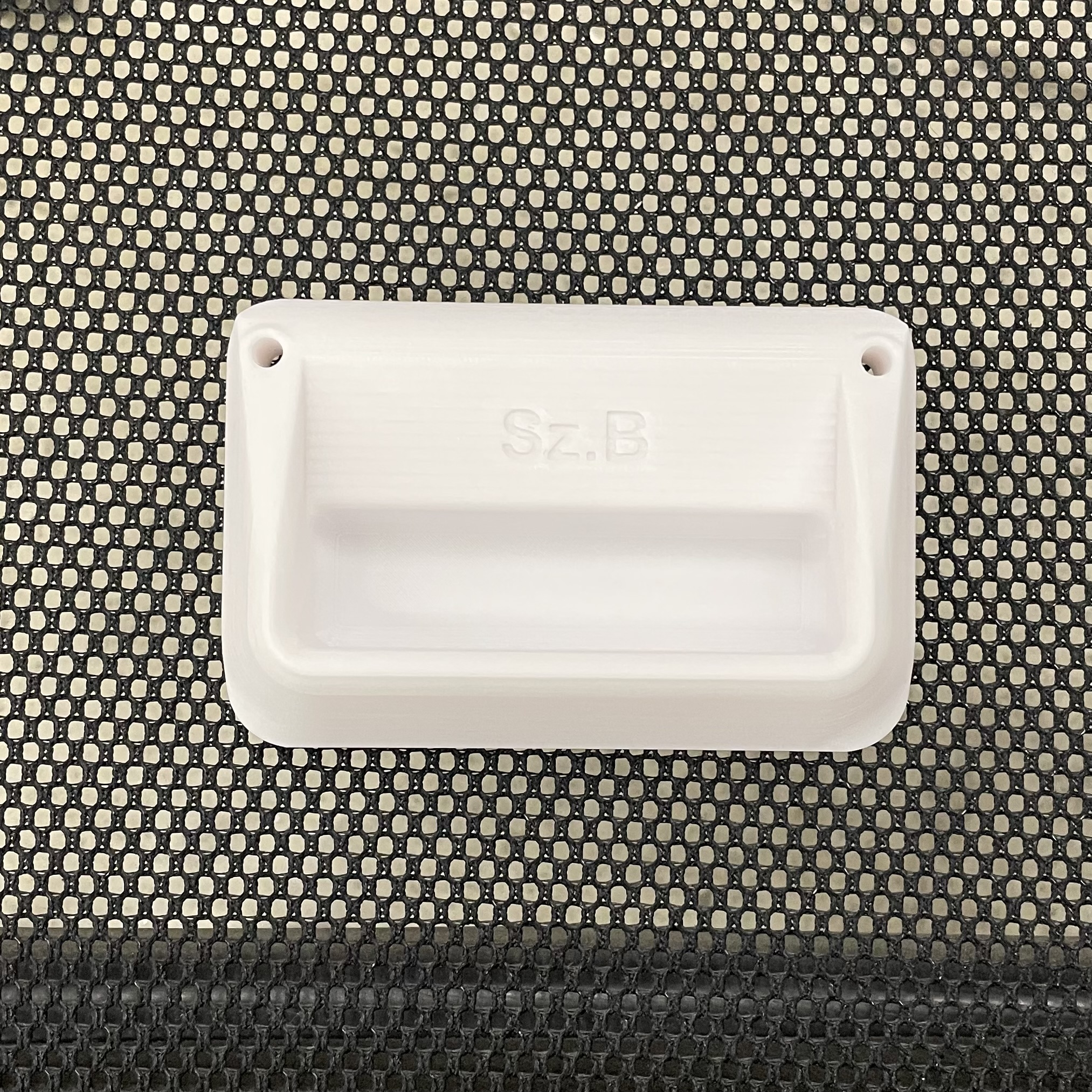
The final part of this project is making the hangboard attachment from which to hang. I found a model for a mini hangboard on Thingiverse with a suitably deep pocket and small size, so I sliced and printed it at about 1.5x size.
-
Files
-
As a reminder, for detailed information on the software for the final project along with
downloadable files, please see the Week 10 assignment.