Week 3
hand tools and fabrication
Assignment Prompt
Create a kinetic sculpture. Include circuitry to move your sculpture. Control the sculpture with a circuit on a breadboard that uses components in the lab (e.g., resistors, potentiometer). Use a multimeter to measure the voltages in your circuit. Use Ohm's law to calculate current through the circuit.
Inspiration
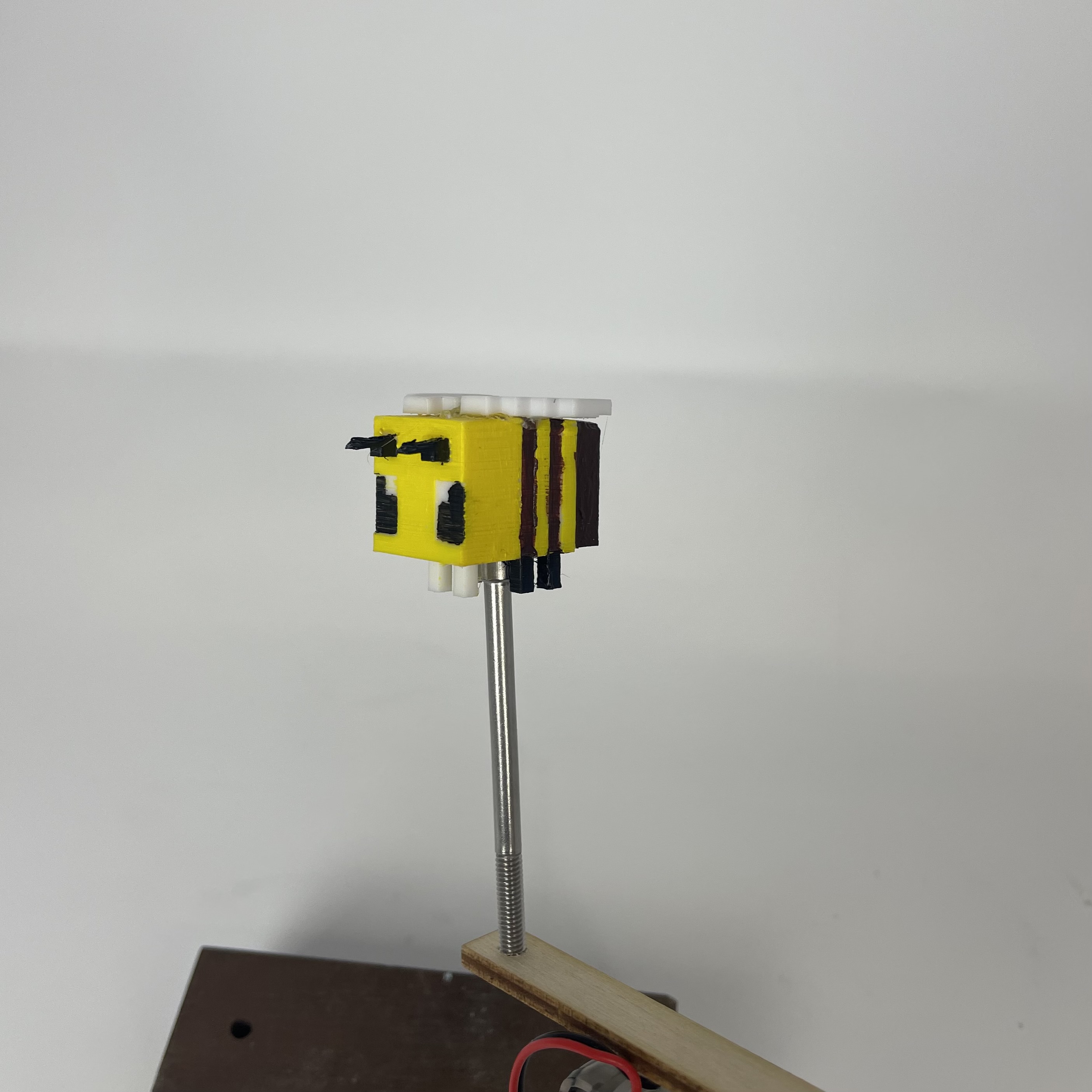
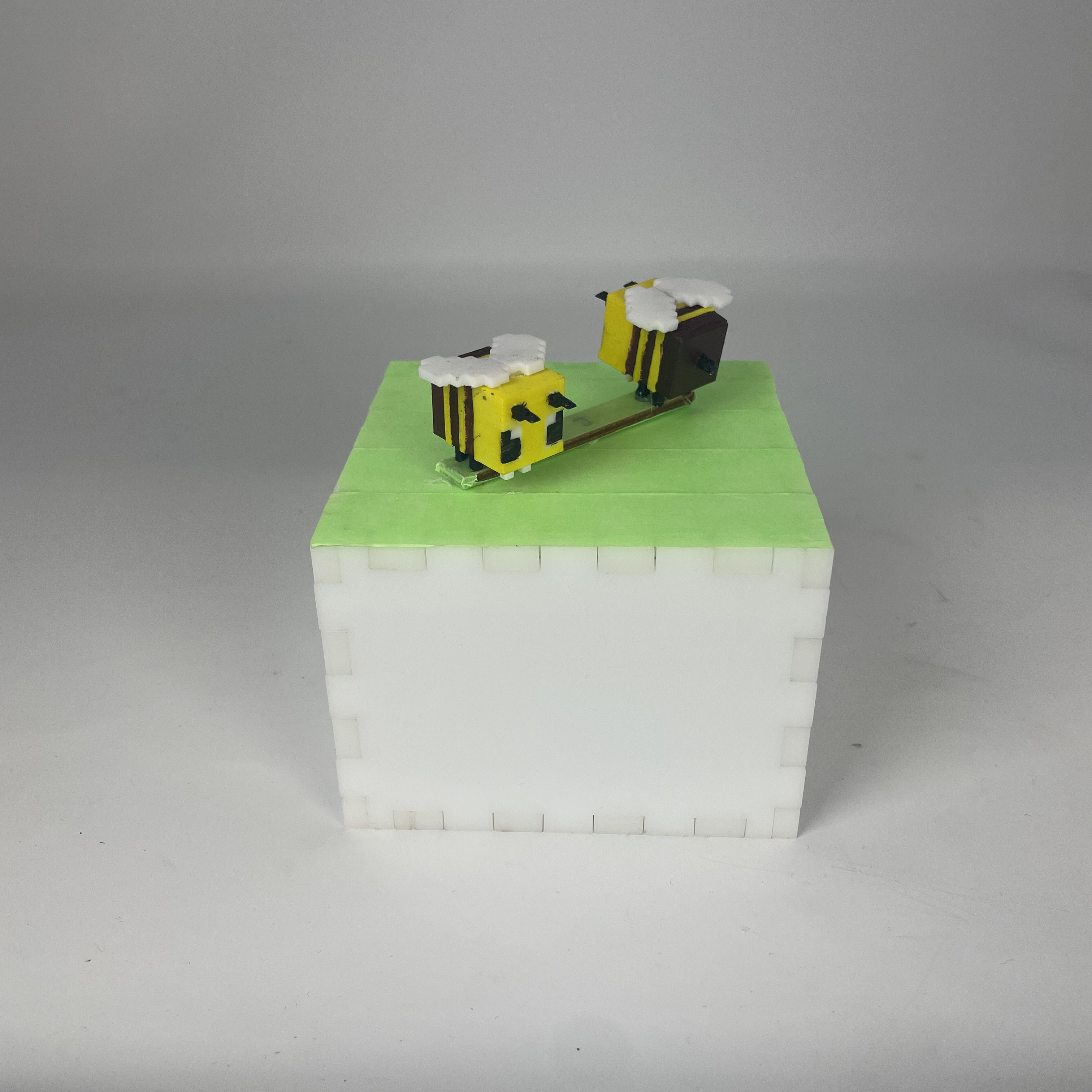
The first iteration of this project, at the start of the semester, was a rotating Minecraft flower whose speed was controlled by potentiometer (photos below). While this project was perfectly and totally fine, I guess I forgot that I made a perfectly and totally fine kinetic sculpture, so I made a second one! This time, I wanted to make two Minecraft bees that flew around in a little meadow.
Circuitry
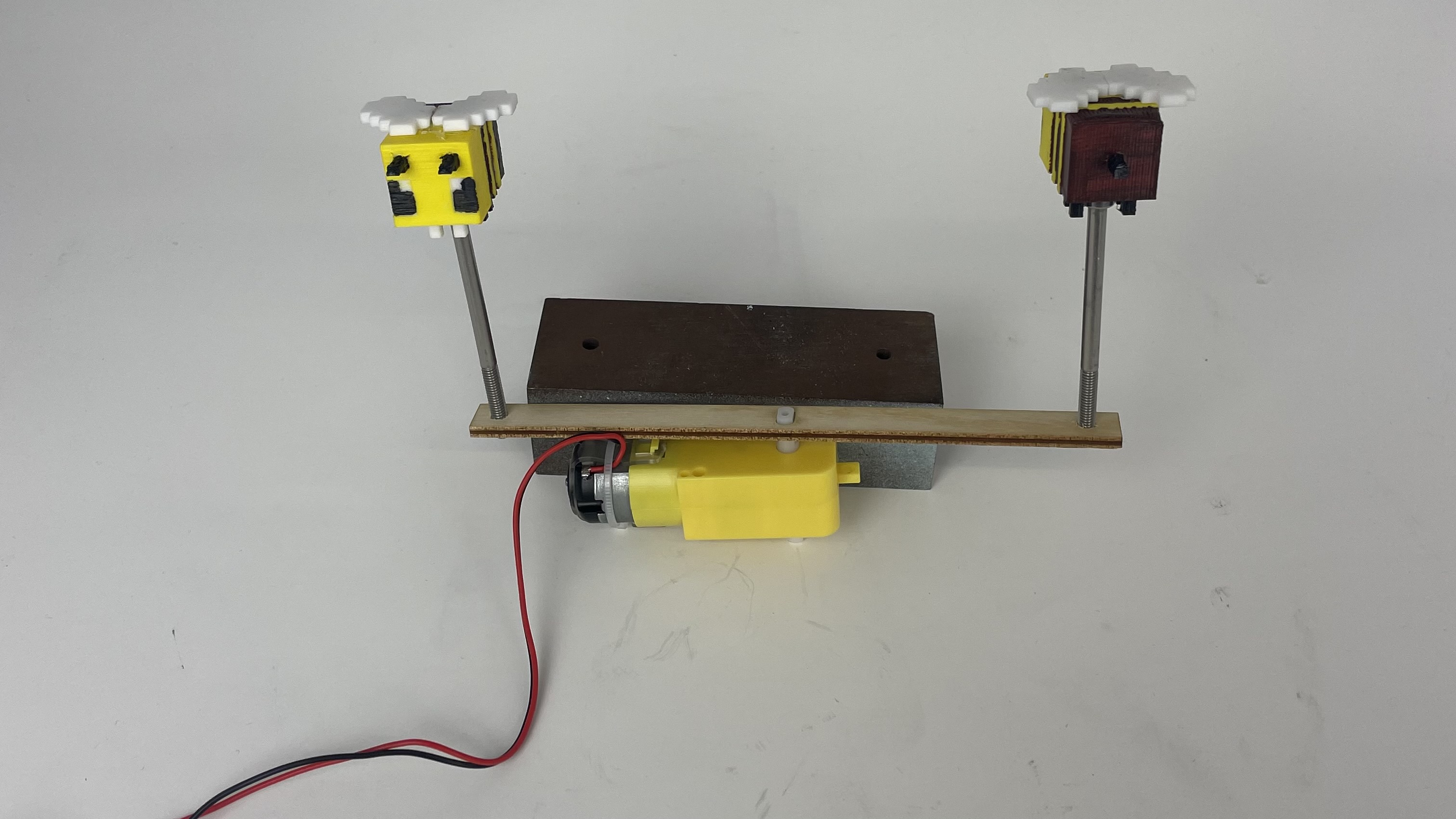
The setup for this project is simple. A yellow motor controls the the spinning of the bees
(pictured), while a button controls the speed of the motor and adds interaction (not
pictured). To facilitate the spinning, I at first made a long "key" that locked into the
axle of the motor and had the bees attached to it by screws, but once I realized that this
design would require an open-top box, I cut the key in length and glued the bees to it
directly.
The two-pin yellow motor uses an L9110 H Bridge Power Driver to drive the motor.
3D Printing and Cutting
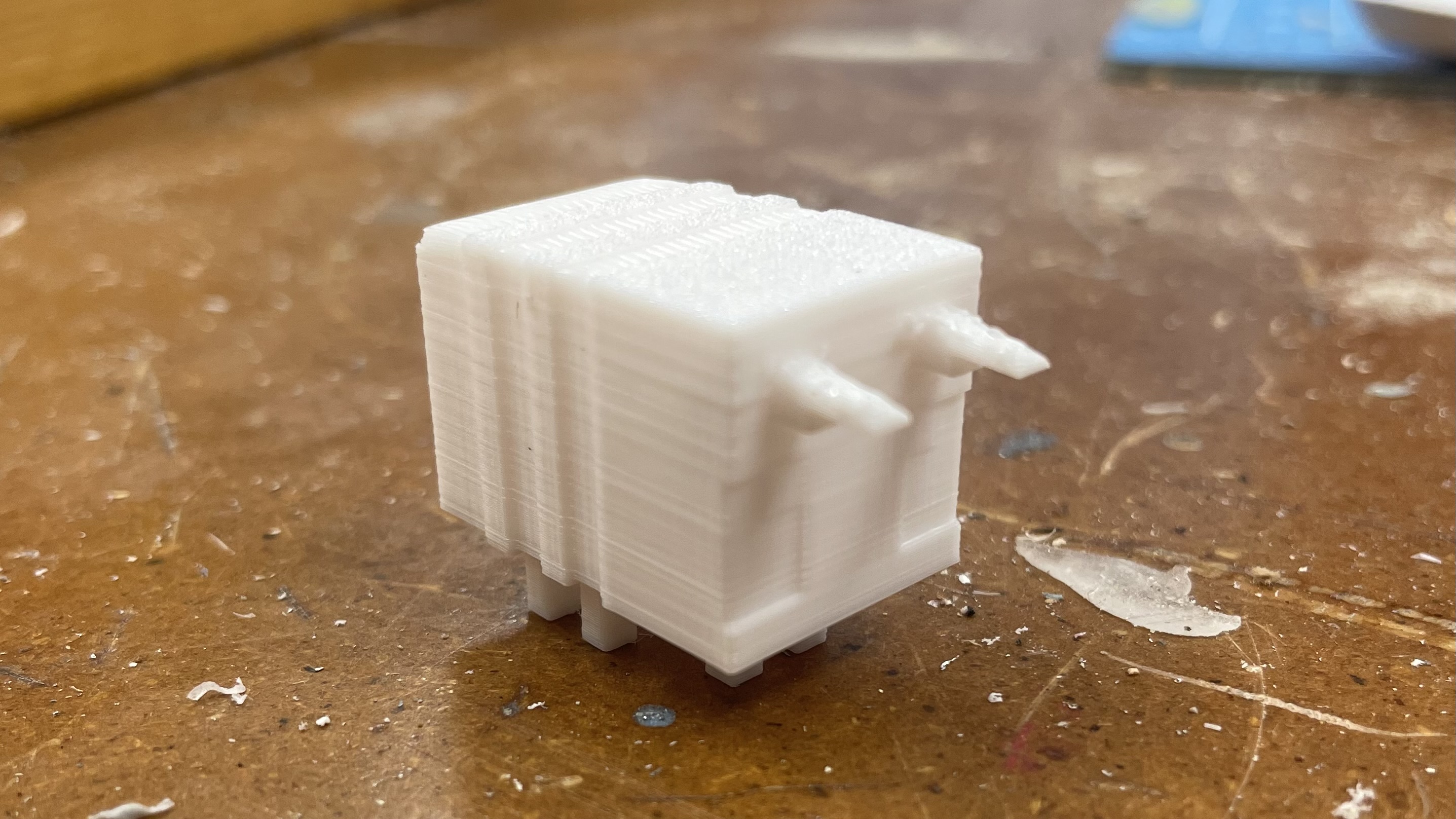
To make the bees, I used a model I found on Printables.
Though it doesn't look the cutest from its photos on Printables, I had faith, and I decided
to print two. They're lightweight and only about an inch long with an infill of about 15%.
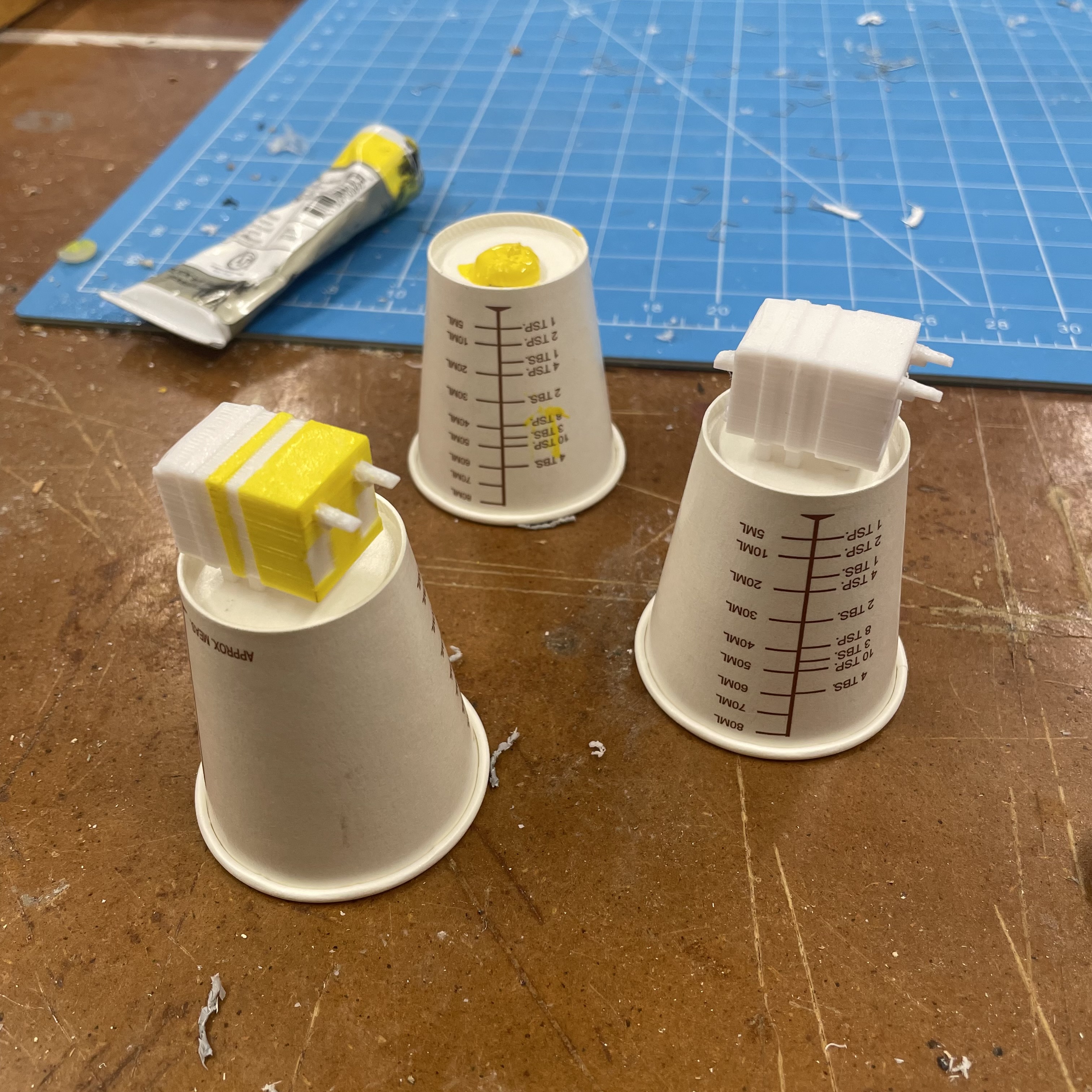
To get them the proper color, I used paints from the lab and a white PLA base for a nice,
empty canvas.
Once the painting was done, I glued the wings on and glued the bees to the key I designed in
Fusion and cut on the laser cutter. The original key length, as pictured below, was fairly
long, but I decided to cut it down by hand once I changed the design and realized the lab
did not have much laser cutting material to make a large box with. After this, I designed a
box that was as small as possible and could hold the equipment. We did not have much
material left, so I ended up using this 6mm thick white acrylic. Painting it took too long,
so to make the "meadow" for the bees to fly in, I used green masking tape. It doesn't look
anything like what I wanted it to, but we live.
Code
The code is simple and somewhat inelegant.
const int A1A = 3;
const int A1B = 4;
const int button = 13;

int speed = 100;

void setup() {
  pinMode(A1A, OUTPUT);
  pinMode(A1B, OUTPUT);
  pinMode(button, INPUT);

  analogWrite(A1A, speed);
  digitalWrite(A1B, LOW);

  Serial.begin(9600);
}

void loop() {
  Serial.println(speed);


  if(digitalRead(button) == HIGH) {
    switch(speed) {
      case 100:
        speed = 150;
        break;

      case 150:
        speed = 200;
        break;

      case 200:
        speed = 100;
        break;
    }
    analogWrite(A1A, speed);
    digitalWrite(A1B, LOW);
    delay(500);
  }
}
You may notice the use of the delay function. The button is used to modulate the speed at which the bees spin. Every time you press it, the speed increases until it reaches a maximum and restarts at the lowest speed. The loop, though, takes less time than the actual pressing of a button, resulting in one button press changing the speed 5-10 times. To counteract this, I added a short delay after the first detection of a button press, after which the user should already have removed their finger. Using the multimeter, I found that, on the low setting, the voltage running through the motor was 2.8V. On medium speed, 3.7V. On the high speed, 4.1V. The voltage running through the button was approximately 3.3V.
Photos
Files
Click the links below to download. To download the STL files for the Minecraft bee, please see the Printables link in the 3D Printing and Cutting section above.